Setting Up AWS MSK

Part 1 – Objectives, Audience, Tools & Prerequisites
Part 2 – Setting Up AWS MSK
Part 3 – Using JavaScript Client To Produce and Consume Events
Part 4 – AWS Lambda Function To Produce Kafka Events
Part 5 – AWS API Gateway For Accepting Events
Part 6 – Consuming Events Using MSK Connect – S3 Bucket Sink
Part 7 – Consuming Events Using AWS ECS
Part 8 – Storing Consumed Events Into AWS RDS
Introduction
In this part of the blog post series we are presenting how you can set up an AWS MSK (Managed Streaming for Apache Kafka) cluster. It is the second part of a series of blog posts in which we are presenting a way to set up an event processing pipeline using Apache Kafka in AWS.
Important: If you follow along the steps suggested in this tutorial, you will probably be charged for the resources created in AWS. Make sure that, at the end of the learning experience, you run the necessary actions to destroy these resources, so that you are not charged for any reason. The command that we use, at the end of the process, to destroy the resources we create with this demo, is:
$ terraform destroyLet’s start.
Architecture
In the following picture, we are presenting the architecture of the system we are going to deploy in AWS.
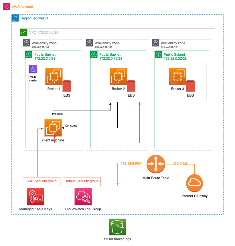
As you can see on the above diagram:
AWS Account
Everything is going to be created in an AWS Account. Hence, make sure that you have already signed up with AWS.
Region
We are going to work on a specific Region. Everything is going to be created in this specific region (“eu-west-1” in the diagram).
VPC
We are going to create a new VPC with IPv4 CIDR block 172.32.0.0/24.
Subnets and Availability Zones
Inside the VPC, we are going to create 3 Subnets. 1 subnet per Availability Zone. We assume here that we have 3 availability zones in eu-west-1 region:
eu-west-1a,eu-west-1bandeu-west-1c.
The 3 subnets that we are going to create will have the following IPv4 CIDR blocks allocated:
eu-west-1asubnet:172.32.0.0/28eu-west-1bsubnet:172.32.0.16/28eu-west-1csubnet:172.32.0.32/28
MSK Cluster
We are going to create an MSK cluster. This is the main objective of this tutorial. The cluster is going to have 3 brokers, each one living in its own availability zone.
EBS Volume
Each one of the brokers is going to have its own EBS volume storage.
Client Machine – EC2 Instance
Inside the 1st subnet, we are going to create an EC2 instance that will be used as a client machine. We are going to ssh to this machine and start a producer and a consumer. Hence we will be able to see how Kafka messages are flowing from the produce to the consumer via the brokers.
Encryption – Kafka Keys
AWS MSK cluster applies encryption at rest, i.e. MSK cluster database saves our data encrypted. For this to take place, a pair of encryption keys is needed. However, we don’t have to create this resource ourselves. We will let AWS MSK creation service to create a pair for us. At the end of the MSK cluster creation process an AWS managed pair of keys will be created and stored in the AWS Key Management Service for the AWS region we are working in.
Note: If you want, you can use your custom managed keys. In that case you will have to create the pair beforehand and provide it inside the encryption_info block as the value of the encryption_at_rest_kms_key_arn attribute.
CloudWatch Log Group
In addition, we are going to create a CloudWatch Log Group. This is the log group where the broker logs will be grouped in. It can be used to inspect what the brokers do or dig into to find any problems.
S3
The actual logs will be stored into an S3 bucket, which is region-independent and lives at the AWS Account level.
Internet Gateway
The VPC will have an Internet Gateway, which will allow traffic to travel in from internet to the VPC, and from VPC out to the internet.
Main VPC Route Table
In order for traffic to travel in from and out to internet via the internet gateway, we have to add one rule to the Main VPC Route Table. We will see the exact rule later on. Note that the main VPC route table will automatically be created when the VPC will be created.
Default Security Group
When we will create the VPC, a Default Security Group will automatically be created. What we will do is to attach it to both the MSK cluster and to the EC2 client machine.
SSH Security Group
We will create an SSH Security Group to attach it to the EC2 client. This will allow us to ssh from our local machine.
Terraform Files
As we said at the beginning, we will use Terraform to describe everything that we want to be part of the AWS architecture for this tutorial. The following shows the files that we will use:
<root>
   |
   -> client_machine.tf
   -> locals.tf
   -> main.tf
   -> terraform.tfvars
   -> variables.tf
In the <root> folder of our project, we will create the above 5 files.
client_machine.tf: It will describe the EC2 client machine related pieceslocals.tf: It is holding the values of expressions that are dynamically calculated and that we don’t want to repeat again and again. See Terraform Local Values here.main.tf: it will describe the MSK cluster and other necessary piecesterraform.tfvars: it will have the values of the Terraform variables in the next filevariables.tf: it will have the Terraform variables that we will use to parameterize the declarations so that it will make it easier to customize the whole project.
Let’s proceed, then, in describing our IaC files.
main.tf
We start with the main.tf, which is the file that describes the MSK cluster and everything else except the EC2 client machine.
The contents of the file main.tf can be downloaded from here.
Let’s have a detailed look into its parts.
Terraform provider
This is the standard Terraform block that declares the provider that we are going to use. It is the hashicorp/aws provider that will allow us to create infrastructure in our AWS Account.
AWS region and profile
We specify the AWS region in which we will create our MSK and the accompanying elements. Also, we specify the AWS profile that will be used to access our AWS account.
VPC
This is where we specify that we want to create a new VPC. The most important piece of information here is the IPv4 CIDR block on line 2.
Moreover, one very good practice, is to assign tags whenever possible. Our minimum recommended tags are:
environmentNameproject
Tags are very useful when you have many projects and environments deployed into the same AWS Account. They help you query and manage these resources much easier. You can read more about tagging here: Tagging AWS Resources.
Internet Gateway
In order to be able to access our cluster from our local machine, we will need an Internet Gateway to be attached to the VPC. Describing the Internet Gateway requires us to define the VPC id it is being attached to.
Route Entry in Route Table
When we create a VPC it has a main route table, but this allows incoming and outgoing traffic only in the boundaries of the VPC. Since we want to be able to connect from our local machine to the EC2 client machine we will have to add one extra route to the main route table. The route is defined by specifying the main route table (line 2), the IPv4 CIDR block for the address that will be treated by this route (line 3) and element the traffic will go in and out to. In this case we specify this element to be our internet gateway (line 4).
Subnets
Our MSK cluster is going to be deployed inside 3 subnets in our VPC. This block defines a series of 3 subnets using the terraform for_each meta-argument technique (see here). Hence, although you see 1 resource entry, it will actually create 3 resources, because the var.vpc_subnets variable is defined as a map with 3 entries:
Extract from variables.tf:
When defining a subnet the most important parts are:
- Availability zone (line 4). This is created as a combination of the region and a suffix. Example:
eu-west-1afor the first subnet. - IPv4 CIDR Block (line 5)
- The VPC to attach to (line 11)
Again, we follow the best practice to define tags to the subnets.
CloudWatch Log Group
This is where the logs of the MSK brokers will be grouped in. Defining a CloudWatch log group is very simple. We only need to define the name (line 2). Besides that, we follow the practice to set tags for this group (lines 3-7).
S3 Broker Logs Bucket
The broker logs are going to be stored inside an S3 bucket, besides to whatever goes to the CloudWatch log group.
Creating an S3 bucket is a little bit more involved. Watch out for the following:
- The bucket name should be globally unique (line 2). That is why we concatenate the company name and the project name as prefix.
- We set
force_destroytotrueand thelifecycle.prevent_destroytofalse(lines 3-6). This will allow us to run theterraform destroywith success and include the S3 bucket in the destroy process. Otherwise, we will not be able to destroy the S3 bucket. - We create an S3 Bucket ACL to make sure the bucket is
private(lines 14-17).
MSK Cluster
That is the bulk of the terraform definition file and the main objective of this tutorial. To create the MSK cluster.
The most important part of this definition are:
Cluster Name
We set a name for our cluster by setting a value to cluster_name.
Kafka Version
We set the Kafka version we want to use by setting a value to kafka_vesion, via the variable var.kafka_version. We have developed this tutorial using the Kafka version 3.2.0.
Number Of Broker Nodes
We go with 3 broker nodes. We set the number to the attribute number_of_broker_nodes via the variable var.number_of_nodes.
Brokers Configuration
We give the brokers configuration inside a block broker_node_group_info. With the az_distribution having the value DEFAULT, one broker will be created in each of the availability zones. We also set the subnets that will be used for the brokers in the client_subnets attribute.
We then disable the public access (connectivity_info).
We specify the instance type using the variable var.brokers.instance_type.
We set the security group the brokers will belong to. It will be the default security group of the VPC, which allows any traffic within the boundaries of the VPC.
Finally, we specify the information about the storage that will be attached to each broker. The storage_info block gives this specification. Note the variable var.brokers.storage_volume_size. This is where you will define the size of the Elastic Block Storage (EBS) that will be attached to each broker.
Encryption
Then we specify the encryption details of the MSK cluster:
The encryption_at_transit specifies whether data are going to be encrypted while traveling either from clients (producers and consumers) to brokers or in-between the brokers of the cluster.
For the encryption between clients and brokers we set the client_broker = 'TLS_PLAINTEXT', hence specifying that both techniques (TLS and plain text, i.e. no encryption) of encryption will be available.
The in_cluster = true setting specifies that encryption at transit will take place for data travelling in-between the brokers of the cluster. This part of the encryption is always using TLS.
Note also that, although it is not specified in any way in the encryption_info block, AWS MSK cluster will apply encryption at rest too. I.e. our data are going to be encrypted inside the MSK cluster database.
Logging Info – Broker Log Delivery
We then specify the logging information for our cluster. The pieces of information given here are related to the requirement of cluster monitoring. I.e. we enable the relevant services so that we can have a basic monitoring about what is going on with our brokers and our cluster.
As you can see from the snippet above, we specify two facilities for logging:
The cloudwatch_logs part specifies that we want our cluster and our brokers to send their logs to AWS CloudWatch service and in particular to the CloudWatch log group we are creating in another part of the terraform file (aws_cloudwatch_log_group.kafka_brokers_log.id). Sending their logs to CloudWatch will allow for analysis, querying and definition of alarms.
The S3 part specifies that we also send the logs to an S3 bucket. These are raw logs that we can keep for as long as we want. When specifying this part of logging configuration, we give the id of the bucket we want to use. It is aws_s3_bucket.broker_logs_bucket.id referring to a resource we create at a previous part of the terraform file. Note also the prefix which can be used to prepend to all the filenames that will be created in the S3 bucket.
Client Authentication
With the above we set the client authentication security settings.
- We allow unauthenticated access. This also means that all actions will be allowed.
- Moreover, we allow for IAM role-based authentication.
Tags
We finish the MSK cluster configuration by applying the best practice to set a series of tags, like we did for previous resources.
Client Machine
Having gone through the configuration of the basic elements and the MSK cluster, we now proceed to the configuration of the client machine. We use the file client_machine.tf to define it.
AMI – Amazon Machine Image
We start by defining which AMI we want to use for the EC2 instance.
When we want to specify an AMI, we, basically, tell Terraform to search for it. We could have gone with a hard-coded AMI id, but we chose to specify some filters for searching. We search by
- Architecture.
- The automatic removal of the block storage device on termination of the EC2 instance.
- Image Type.
- To be public.
- Virtualization Type.
- Name pattern.
- Root device type.
- Owner.
We have tested this and it returns an AMI available in the AWS region we want to build our cluster in.
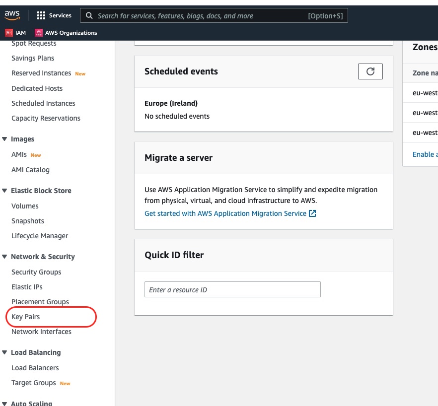
EC2 Key Pair
In order to be able to connect to the EC2 instance, we will an EC2 Key Pair. This needs to be already created beforehand. If you don’t have one, visit the AWS Console EC2 service and then there is an option to access and create key pairs on the bottom left, in the Network and Security area.
In the Terraform client_machine.tf file we write:
We set the key_name as we had already named our key pair and stored it in the AWS EC2 Key Pairs console.
Security Group – Allow SSH Traffic
The presence of the EC2 key pair is not enough. We need to allow ssh incoming and outgoing traffic to the EC2 instance. This is done with a new security group we create:
The security group is attached to the VPC we create (line 4).
Then, it has two blocks of configuration. One for the incoming traffic (ingres) and one for the outgoing traffic (egres). We allow incoming traffic only on the port 22, which is the standard ssh port. We allow outgoing traffic over any port.
Finally, we tag this security group with the usual tags.
EC2 Instance
The main block for the client machine is the block that defines the configuration of the EC2 instance itself:
- On line 2, we set the AMI that will be used for the instance.
- Then, line 3, we specify the instance type. You can go with a
t2.microinstance type. - We specify the availability zone and the subnet it is going to be created in. We will create it inside the first availability zone and the first subnet.
- Then (lines 6 – 9), we specify the security groups that will be attached to the EC2 instance. We define two security groups. The default VPC security group, that will allow access from the client machine to the cluster, and the ssh security group we created earlier, which will allow us to connect via ssh from our local machine.
- In lines 19 – 31, we make sure that we export the value of the environment variables with names
KAFKA_BROKERSandTOPIC_NAME.- We set
KAFKA_BROKERSvariable to take the value ofaws_msk_cluster.msk_cluster.bootstrap_brokers, i.e. the part of the output of the creation of the resourceaws_msk_cluster.msk_clusterthat contains the urls of the Kafka brokers, necessary for the clients to connect for publishing, consuming and other management commands. The fact that we use the output of the creation of another resource (MSK cluster), it makes this resource (the ec2 instance) to depend on the other (MSK cluster). - For the
TOPIC_NAMEwe export it to have the value of the variablevar.topic_name. This makes it easy to later on refer to this Kafka topic.
- We set
- In lines 33 – 48, we make sure that some of the necessary software for Kafka client to run is installed.
- We use the terraform configuration block which is called remote-exec Provisioner.
- The remote-exec provisioner requires a
connectionblock (lines 34 – 39).- The connection block specifies how Terraform is going to connect to the created instance. We use the
sshtype of connection. Hence, we need to provide theuser, thehostand either apasswordor aprivate_key. Thehostis specified usingself.public_ip. Theself.public_ipis holding the public IP of the EC2 instance after it has been created. Theprivate_keytakes the value of the contents of the file that is locally, in our local host machine that runs Terraform, stored. - Between line 41 and 47 we specify the commands that the provisioner needs to execute at the new instantiated client machine.
- line 42: First, we install the Java programming language.
- line 43: Then we download the Kafka archive.
- line 44: We unarchive the Kafka archive, which creates the Kafka folder where all the Kafka software and client tools resides in.
- line 45: We create the file
client.propertieshaving the configuration valuesecurity.protocol=PLAINTEXTto make sure that we allow the plain text communication. - line 46: We create the Kafka topic in which we will be publishing messages into. Note that the EC2 client machine is created after the MSK cluster is ready. Hence, we can use the client tools (like the
./bin/kafka-topics.sh) to communicate with the Kafka brokers.
- The connection block specifies how Terraform is going to connect to the created instance. We use the
We don’t forget the practice of tagging (lines 13 – 17).
Terraform Variables and Input Values
For the sake of completeness, we give here the content of the file variables.tf and terraform.tfvars.
Variables
The file variables.tf contains the Terraform variables that can be used to easily configure the way this Terraform setup works.
Some of the most interesting parts of this piece of code are:
- The variable type for the subnets, i.e. the
vpc_subnetsvariable. It is amap(object({...})). This is a nice way to specify a structured type. - The variable
brokers, which is anobject({...})that has avalidationrule on the values that theinstance_typecan take. - Note also the variable
topic_namewhich has the default valuelive-listening-events. This is where we will be publishing events into.
Input Values – terraform.tfvars
Here, you can see an example of input values to be provided when applying the Terraform plan.
Create Infrastructure
We have seen the whole Terraform configuration for what we want to achieve. Now it is time to create this whole set of resources by applying this configuration. This is done with the command:
$ terraform applyFirstly, Terraform will present to us a list of actions that the configuration corresponds to. We will have to accept the actions by answering yes. When we approve, Terraform will create the resources by connecting to our AWS account.
Note: The MSK cluster takes a lot of time to be created. It took about 30 minutes to be created on my end.
Demo – Produce and Consume Events
As soon as the configuration has been applied, we will be able to use the new resources and demonstrate the production and consumption of events. Here is how we can do it:
Connect to the EC2 Client Machine
We will use ssh to connect to our EC2 client. In order to do that we need to have access to the private part of the ssh key and to the domain name of the EC2 client machine. The domain name we can take it from the AWS EC2 console:
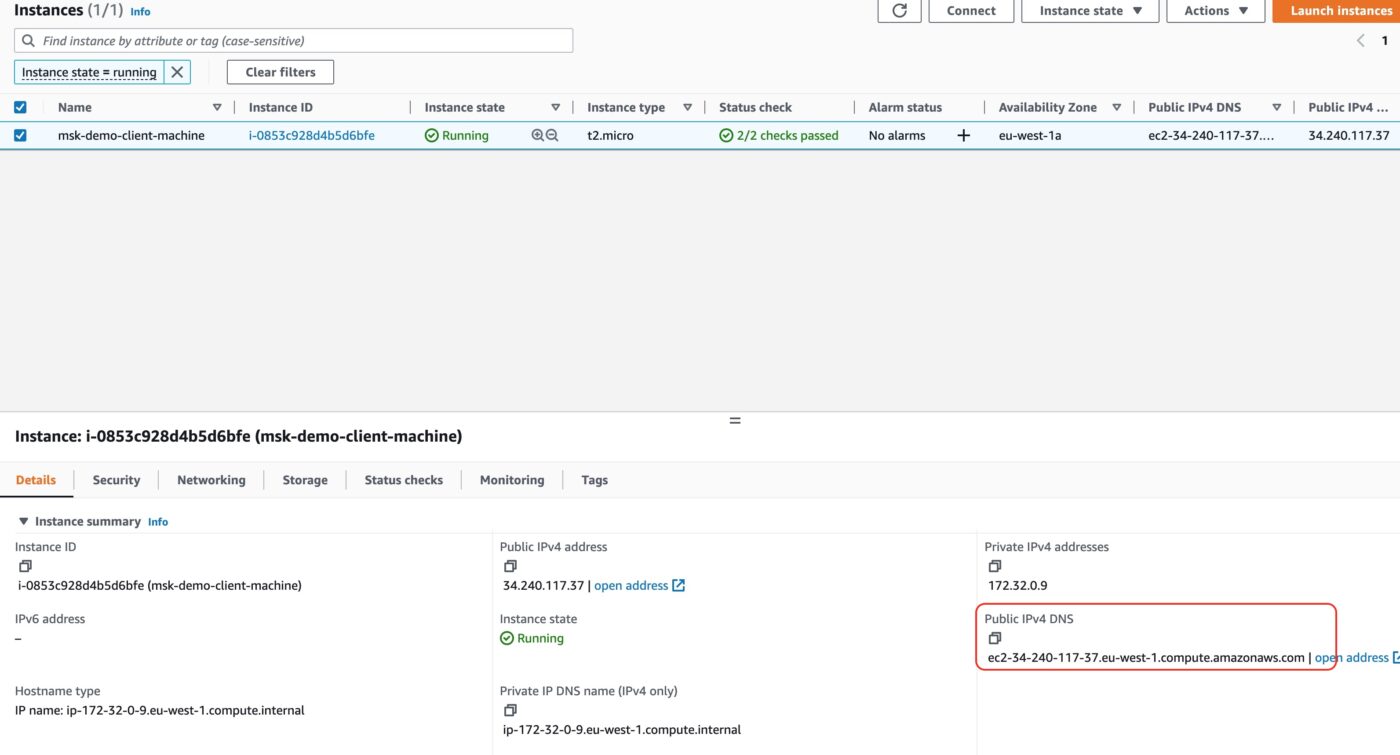
Copy the Public IPv4 DNS and use it in the following command:
$ ssh -i ~/.ssh/me-ireland.pem ec2-user@ec2-63-32-92-24.eu-west-1.compute.amazonaws.comMake sure that you use your own pem file and the Public DNS for your own EC2 client machine.
The above command will give you access to the shell of your EC2 client machine. This is where we are going to take the next action.
Change Working Directory to Kafka Installation Folder
$ cd kafka_2.13-3.2.0/Produce Events
We can now start producing some events. Please, remember that the topic live-listening-events is already created thanks to the remote-exec inside the client_machine.tf.
We run the following command to start a producer. This producer is shipped with Kafka as a demo producer. Whatever line we type in the console window, it will be published as a new event. Here is how to start it:
$ ./bin/kafka-console-producer.sh --bootstrap-server ${KAFKA_BROKERS} --producer.config ./bin/client.properties --topic ${TOPIC_NAME}As soon as we fire the above command we will be in a new prompt >. There, we can type in lines of messages. Each line will be a separate message to be produced/published. Here is an example:
[ec2-user@ip-172-32-0-9 kafka_2.13-3.2.0]$ ./bin/kafka-console-producer.sh --bootstrap-server ${KAFKA_BROKERS} --producer.config ./bin/client.properties --topic ${TOPIC_NAME}
OpenJDK 64-Bit Server VM warning: If the number of processors is expected to increase from one, then you should configure the number of parallel GC threads appropriately using -XX:ParallelGCThreads=N
>Message 1
>Message 2
>Message 3
>
We published 3 messages. There is nothing more to see here. The next step is that we start a consumer that will consume the published messages.
Consume Events
We leave the producer terminal up and running. We now use ssh to connect to the client machine from another terminal. In this second terminal we will start a consumer and we will see it consuming messages produced by the producer on the first terminal.
$ ssh -i ~/.ssh/me-ireland.pem ec2-user@ec2-63-32-92-24.eu-west-1.compute.amazonaws.comThen cd to the Kafka instalation:
$ cd kafka_2.13-3.2.0/With the second / new connection terminal, we start the consumer with the following command:
$ ./bin/kafka-console-consumer.sh --bootstrap-server ${KAFKA_BROKERS} --consumer.config ./bin/client.properties --topic ${TOPIC_NAME} --from-beginningAs soon as you start the consumer you will see that it immediately consumes the messages that have been previously produced by our producer:
$ ./bin/kafka-console-consumer.sh --bootstrap-server ${KAFKA_BROKERS} --consumer.config ./bin/client.properties --topic ${TOPIC_NAME} --from-beginning
OpenJDK 64-Bit Server VM warning: If the number of processors is expected to increase from one, then you should configure the number of parallel GC threads appropriately using -XX:ParallelGCThreads=N
Message 1
Message 2
Message 3
If you go back to the first terminal, where the producer is running, and type in a new message line, then you will see that immediately appearing in the consumer terminal.
Awesome! We have managed to produce and consume Kafka events!
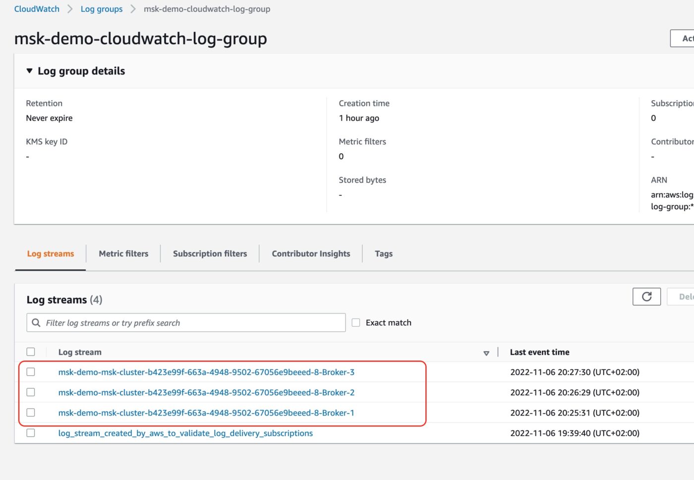
Broker Logs
Before we end this demo, let’s have a look at the logs the brokers are generating. We visit the AWS CloudWatch service. There we click on Log groups to see the entry of the Log group we have created.
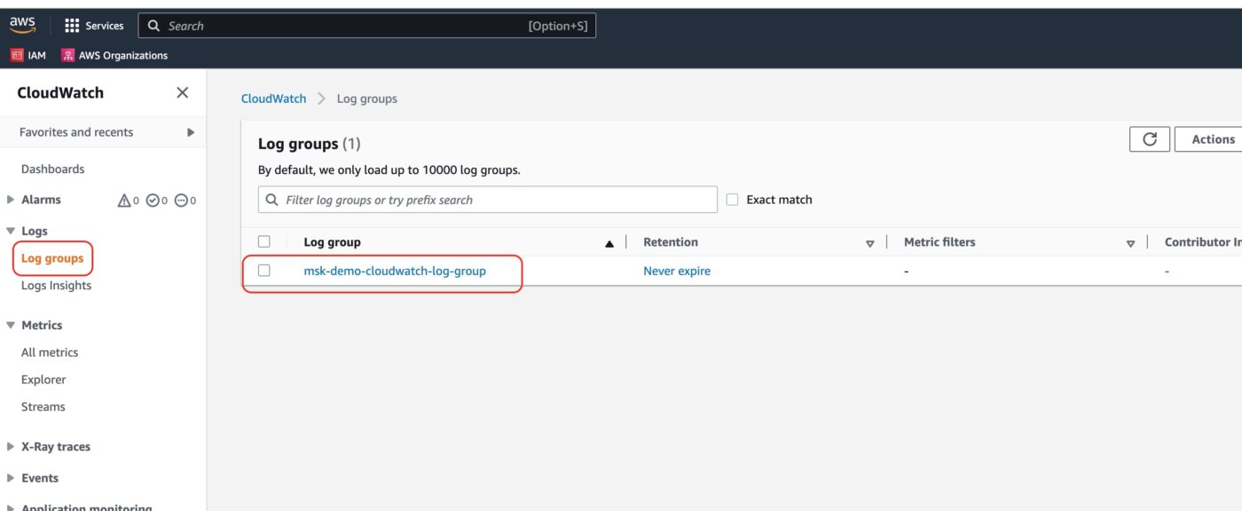
If we click to see the details of the log group, we will see the three logs streams of the log group, one for each of the MSK cluster brokers.
Another interested part of the AWS CloudWatch service is the Metrics dashboard. You can access it from the left-side menu:
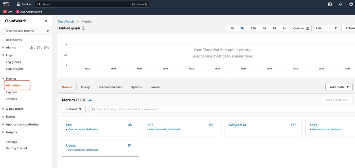
We choose the AWS/Kafka metrics block.
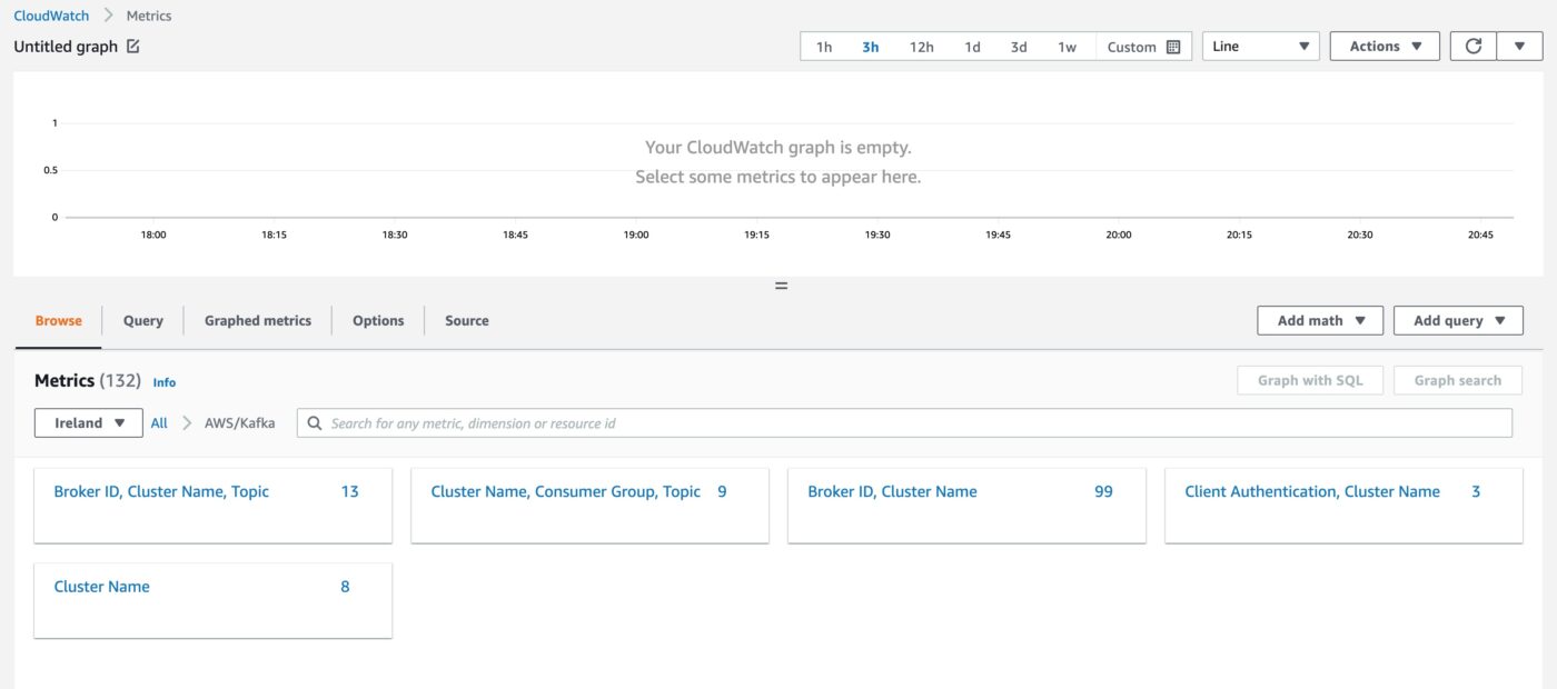
We can now see various metrics blocks which are related to the AWS Kafka service. If we choose, for example, Cluster Name, we will see cluster-level metrics.
Delete Resources
This is the end of the demo. In order to avoid consuming AWS resources and incur more charges to our AWS account, we follow the next steps to delete all the resources that we have created. Again, Terraform plays significant role here, because it will help delete all the created resources very easily.
First, we exit the two terminal sessions that we have created for the producer and the consumer.
Then, from our local terminal, where our working folder is, we run the command:
$ terraform destroyTerraform will identify 12 resources to be destroy. Type in yes and hit the <Enter> key. It will take some time for the resources to be destroyed. Leave the terminal with the Terraform command running until Terraform tells you have everything has been applied.
Closing Note
That is the end of Part 2 of the tutorial series Practical Terraform & AWS. We will continue with the third Part Using JavaScript Client to Produce and Consume Events.
Contact Me
If you want to contact me to ask questions and provide feedback and comments, you are more than welcome to do it. My name is Panos and my email is panos@mixlr.com.